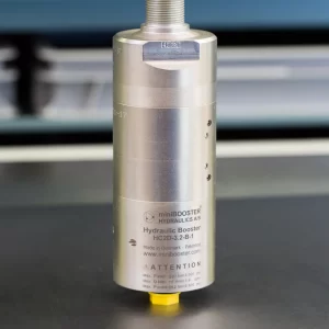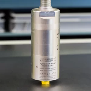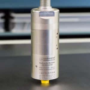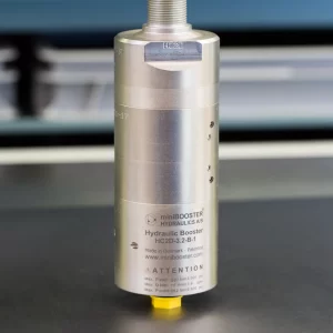
MiniBOOSTER Hydraulic Intensifier M-HC6-002-3.3-A-1
- Payment by invoice possible
- Not currently in stock, contact us for factory lead times
- Payment by invoice possible
- In stock at factory, ready to ship in estimated 1-2 weeks, contact us for expedited options
- Del Rey is proud to be the exclusive distributor of Waagene products
- Payment by invoice possible
- Low quantities typically kept on hand; please contact us for availability at lead time
- Authorized MiniBOOSTER distributor & hydraulic excellence partner
Product Description
The HC6 – 3.3 – A – 1 is a complete, ready-to-install, high-flow and high-pressure intensifier system. The system is based on the miniBOOSTER HC6 intensifier and includes integral high-flow bypass and isolation valves.
The intensifier system M-HC6-004 also includes a relief valve on the HP-side.
The system is ideal for mobile attachments to take full advantage of the pump capacity for fast-forward movement of the hydraulic cylinder(s) and to boost pressure, when needed to achieve intensified (crushing/clamping) pressures.
The M-HC6 intensifier system can be tailor-made to match your application.
Typical applications
Mobile attachments; motors – steering systems – cutters – crushers – shears, off highway equipment, injection molding machines and hydraulic presses.
Additional information
Product Specifications
- Automatically activated (sequence valve).
- Flexible design; several intensification factors.
- Multiple connection possibilities.
- Extended service life.
- Robust design
- PIN: 20 – 300 bar
- PH: 500 bar maximum.
- Q: 100 L/min.
- Weight: 23.0 kg/ 50.7 Lbs.
Function Diagram
Function Diagram M-HC6-002-3.3-A-1

Dimension Diagram
Dimension Diagram M-HC6-002-3.3-A-1
Connection Types
| Connection | P / T / Z | H | P1 / T1 |
|---|---|---|---|
| M-HC6-001 | 1/2″ BSPP | Flange | 3/8″ BSPP |
| M-HC6-002 | 1/2″ BSPP | Flange | 1/2″ BSPP |
| M-HC6-003 | 1/2″ BSPP | 1/2″ BSPP | 3/8″ BSPP |
| M-HC6-004 | 1/2″ BSPP | 1/2″ BSPP | 3/8″ BSPP |
Ordering example of an M-HC6
An intensifier system M-HC6 for 500 bar 100 l/min with 1/2” BSPP thread connection on high-pressure side for tube mounting, mounted with an HC6 – 3.3 – A – 1:
M-HC6-002 mounted with HC6 – 3.3 – A – 1
Attention note!
Valve pre-settings are required, please specify when ordering the intensifier system.
Selection of intensifier system
| Ordering code | Connection | Bypass flow | Max. pressure | Weight |
|---|---|---|---|---|
| M-HC6-001 | Flange | 100 l/min | 500 bar | 23.0 kg |
| M-HC6-002 | Flange | 100 l/min | 500 bar | 23.0 kg |
| M-HC6-003 | Tube | 100 l/min | 500 bar | 23.0 kg |
| M-HC6-004 | Tube | 100 l/min | 500 bar | 23.0 kg |
Selection of intensification factor
| Model | Intensification | Model version | Connection |
|---|---|---|---|
| HC6 | 1.3 | A | 1 |
| HC6 | 1.5 | A | 1 |
| HC6 | 1.9 | A | 1 |
| HC6 | 2.5 | A | 1 |
| HC6 | 3.3 | A | 1 |
| HC6 | 4.0 | A | 1 |
| HC6 | 4.9 | A | 1 |
| HC6 | 6.3 | A | 1 |
| HC6 | 8.2 | A | 1 |
The intensification factor depends on available inlet and desired outlet pressure. To calculate the initial factor, use the following formular:
i = Desired high pressure / pump pressure
Desired pressure: 500 bar
Pump pressure: 207 bar
i = 500 / 207 = 2.4
For static use: Select an intensification factor higher or equal to the calculated value. In this example calculated i = 3.3, select factor i = 3.3. For M-HC6-004 only: The desired pressure of 500 bar is finally adjusted with the Pressure Reducing Valve (5).
For dynamic use: Select an intensification factor 40% higher than the calculated value. In this example calculated i = 500 / 207 = 2.4 + 40% = 3.4, select factor i = 3.3. The desired pressure of 500 bar is finally adjusted with the Relief Valve (6).
Max. tightening torque
| P / T / Z | H | |
| 1/2″ BSPP | 1/2″ BSPP | |
| with steel washer | 13.0 da/Nm | 13.0 da/Nm |
| with cutting edge | 13.0 da/Nm | 13.0 da/Nm |
Max. tightening torque flange mounting
| Mounting bolt | |
| M6 12.9 | 1.8 da/Nm |


